![]()
Visit also my recording studio homepage! www.tsrecords.at
How to build a display and meter unit for Tascam US2400 and Nuendo
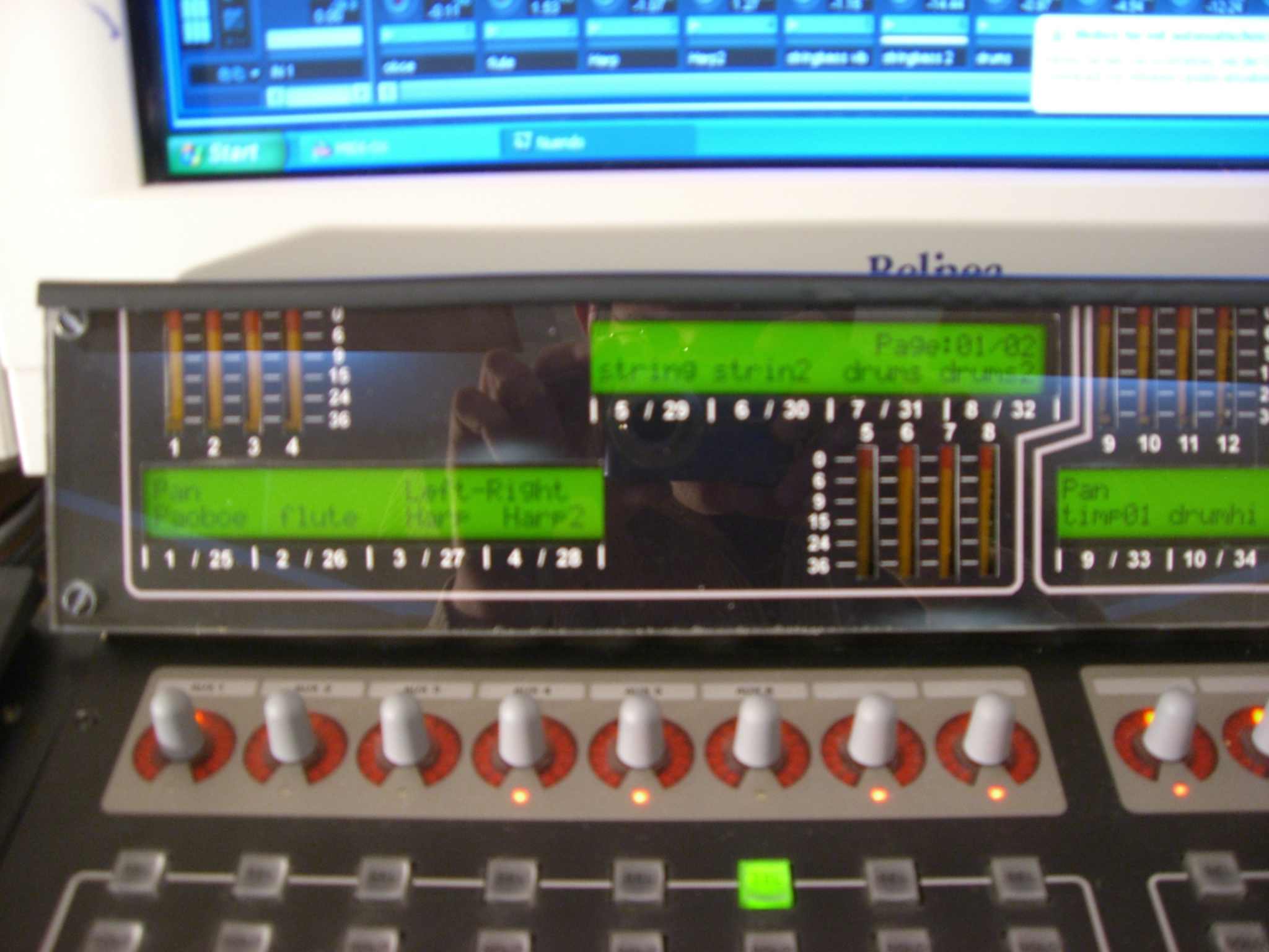
The display and meter unit provides the following functions:
1. Track name for 24
channels.
2. Pan settings for 24 channels.
3. EQ settings, displayed on 4 of the 6 displays, if
you push the EQ button on the US2400.
4. Effect settings if you push the effect send button
on the US2400.
5. Metering for 24 channels.
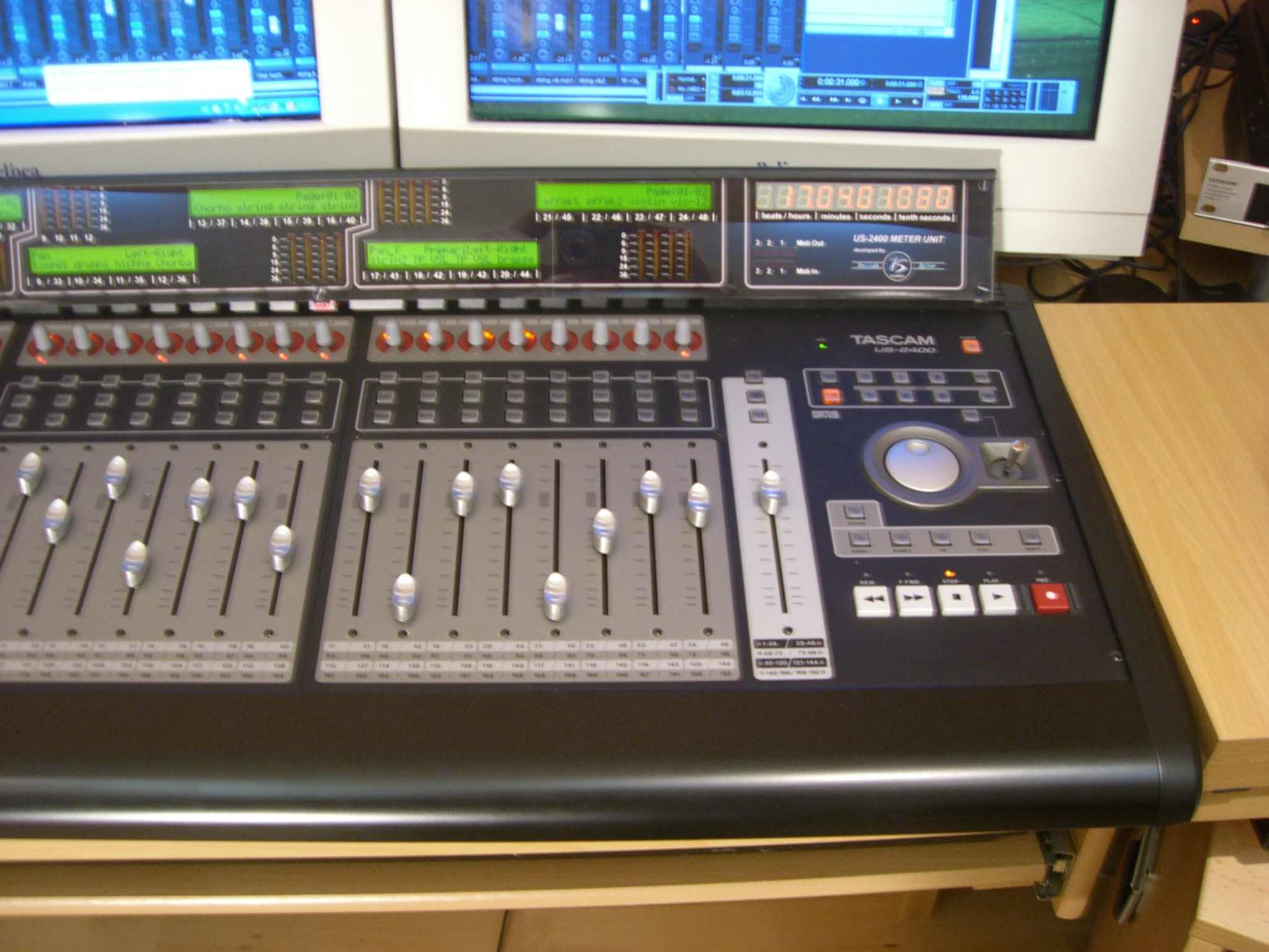
6. Time code bar digits.
7. Settings for dynamic and instrument is currently
under construction.
The costs for the display and meter unit are about 600EUR.
For hyperlink to the different sections click on the pictures and on the blue marked words!
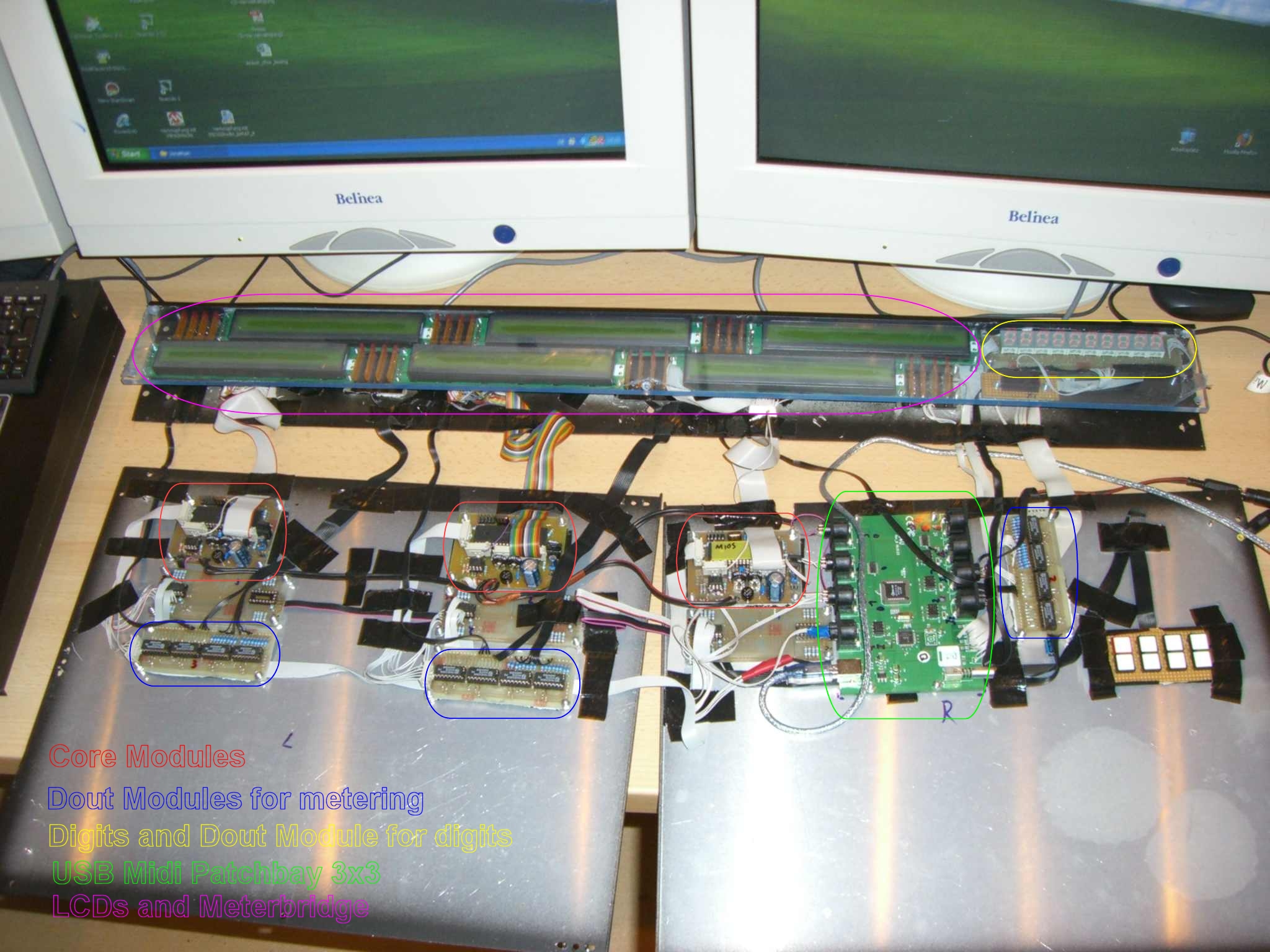
The hardware and programming for the
display unit is based on the core modules and different interfaces of the
Midibox Forum
http://www.ucapps.de/
. Before you start with your display unit read through the basics of the midibox
controller.
Here you can find some good descriptions what is midibox and
how it works.
http://www.midibox.org/dokuwiki/doku.php?id=what_is_a_midibox
http://www.ucapps.de/mios.html
If you are completely confused now, don’t worry it sounds more complicate than it is.
At
first you have to build the core module. You can find the schematics under
http://www.ucapps.de/
MB Hardwareplattform Core
Module. Here you can find
the schematic, the board , the order list and a detailed
description for the core module.
For schematic and board you will need Eagle 4.0 or higher.
You can get it here.
http://www.cadsoft.de/download.htm
You will need three core modules for 24 channels and an USB midi patch bay with
3 midi in and out ports for three core modules (see details on picture)
You
also need a power supply that provides you a voltage of 7-10V and a current of
2A. Before you build the complete setup, try to get one core module with two
displays working.
Attention! You
have to ground the pins on the core module which are normally used for
the fader pack (A0- A7 on pin board J5) otherwise the core
module gets confused.
At next you need the displays. There are 6 “2x40 dot matrix LCDs” needed. One display cost about 40Eur. I know this is expensive! It is very important that you buy displays with background lightning otherwise you won’t see enough because the contrast is very bad at cheep LCDs. I tried it with 5Eur LCDs from eBay, it was horrible. Here you can find the plan for wiring the displays to the core module. http://www.ucapps.de/midibox_lc.html under Connection diagram for 2 2x40 displays. Here is a general specification for 2x40 LCDs as pdf document.
If this work is done
read throw the trouble shooting page for the core module
http://www.ucapps.de/howto_debug_midi.html
If everything is
correct you need to connect the core module with your midi interface.
Now you need
to burn the mios software (download here
http://www.ucapps.de/mios_download.html ) on the PIC via PIC programmer.
If you can
not get a pic programmer you can also buy a pic with mios on it at the midibox
forum. When the mios software is on the PIC you can program it via midi ports.
At next you have to download the Mios Studio (http://www.ucapps.de/mios_download.html
) and my updated version
mackie
control emulation for the core
module
.
I have done a lot of changes in the
original software to get it compatible to the US2400 controller. You can also
download the original software from (http://www.ucapps.de/mios_download.html
) and program it
by yourself, but it is a lot easier to use my version. At the end of the
document I will
describe what I’ve changed in the original software.
With the Mios Studio you can copy the mackie emulation
software to the PIC in the Core Module. Under this link you can find a detailed
description of the Mios Studio and how to handle it.
http://www.ucapps.de/mios_bootstrap_newbies.html
When this is done you should see on the displays “ TASCAM US2400 Display
Unit
”.
If nothing works go back to the trouble shooting page.
http://www.ucapps.de/howto_debug_midi.html
At next we go on with the “time code bar digits” and the metering. You can find the schematic under http://www.ucapps.de/midibox_lc.html in midibox_lc_leddigits.pdf and midibox_lc_ledrings_meters.pdf. Here you can find my board and my schematic that I’ve developed for the digits. The layout and description is under http://www.ucapps.de/mbhp_dout.html. For the time code bar and the metering we need the dout module which is connected to the core module. The time code bar is connected to the first core module. I programmed the software in a way that the dout module for the metering is first connected to the core module and the dout module for the time code bar is connected to the dout module of the metering. (see picture below).
Attention! In the midibox_lc_leddigit.pdf is a mistake in the schematic. The pinning to the digits dot,a,b,c,d,e,f,g on the module is wrong. It has to be flipped g,f,e,d,c,b,a,dot ! If the digits show stupid signs you have connected them with the wrong pinning.
For the metering Dout Module you just need the pins which go to the meter leds because we don’t use the rotary encoders.(they are also disabled in the emulation software). Here is the schematic and board of my metering section. If the first core module is working with the displays, digits and metering you can build the other core modules in the same way.
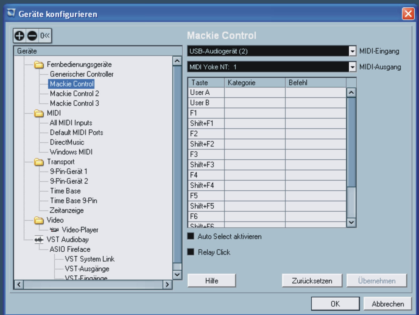
How to test the modules with nuendo.
Start nuendo or
other recording software, go to the controller settings where the US2400 is
installed. For the first test, change the midi out ports from US2400 to the ports
of your core module.
Now you should see on the display a graphic of your recording software.
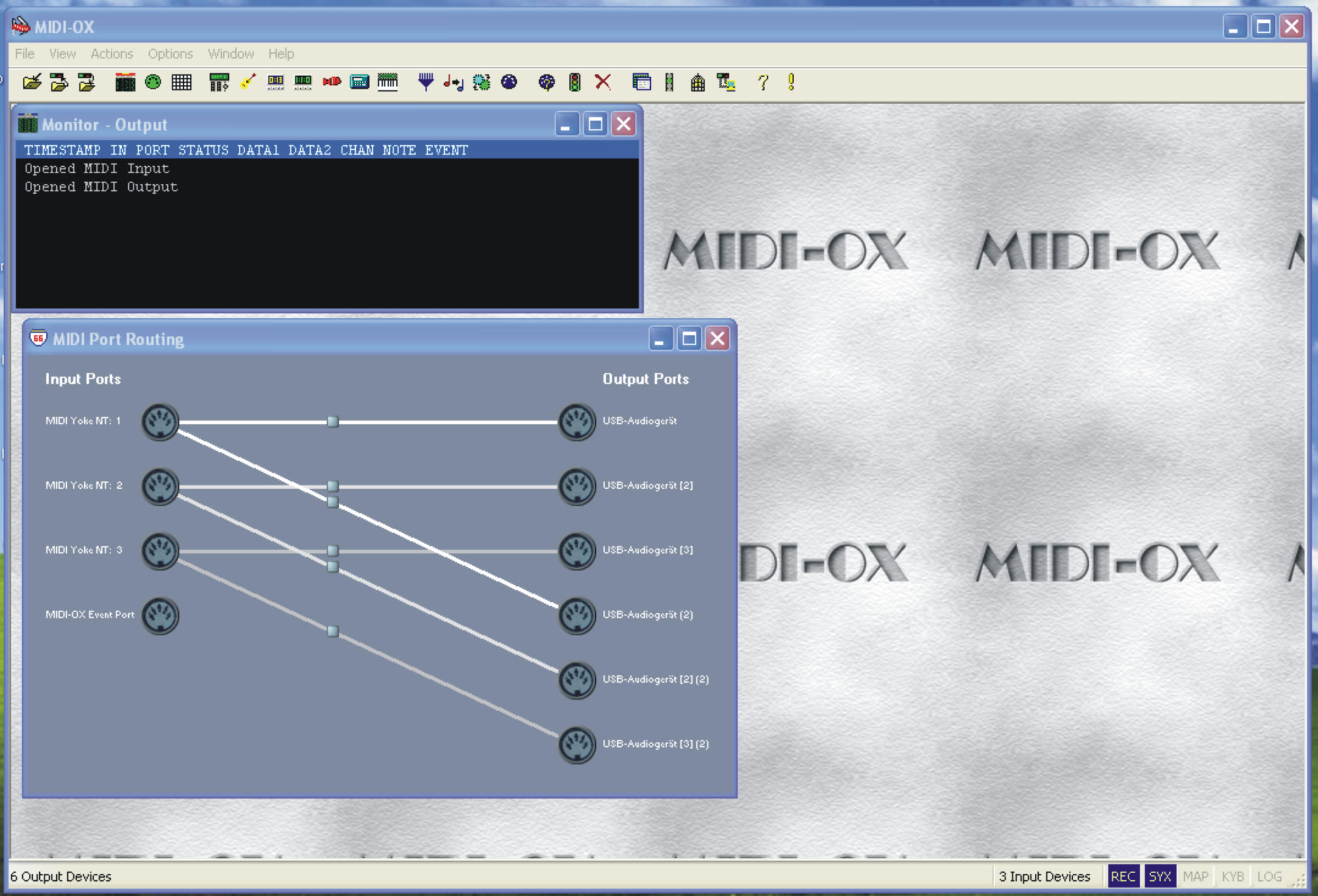
If you want to use
it in combination with the US2400 you have to use ‘midi ox’
and ‘midi yoke’ (download here
http://www.midiox.com/ ).
Midi yoke is a virtual midi port and midi ox can split the midi out of your
recording software to two midi ports, for our use, to the US2400 and the core
module.
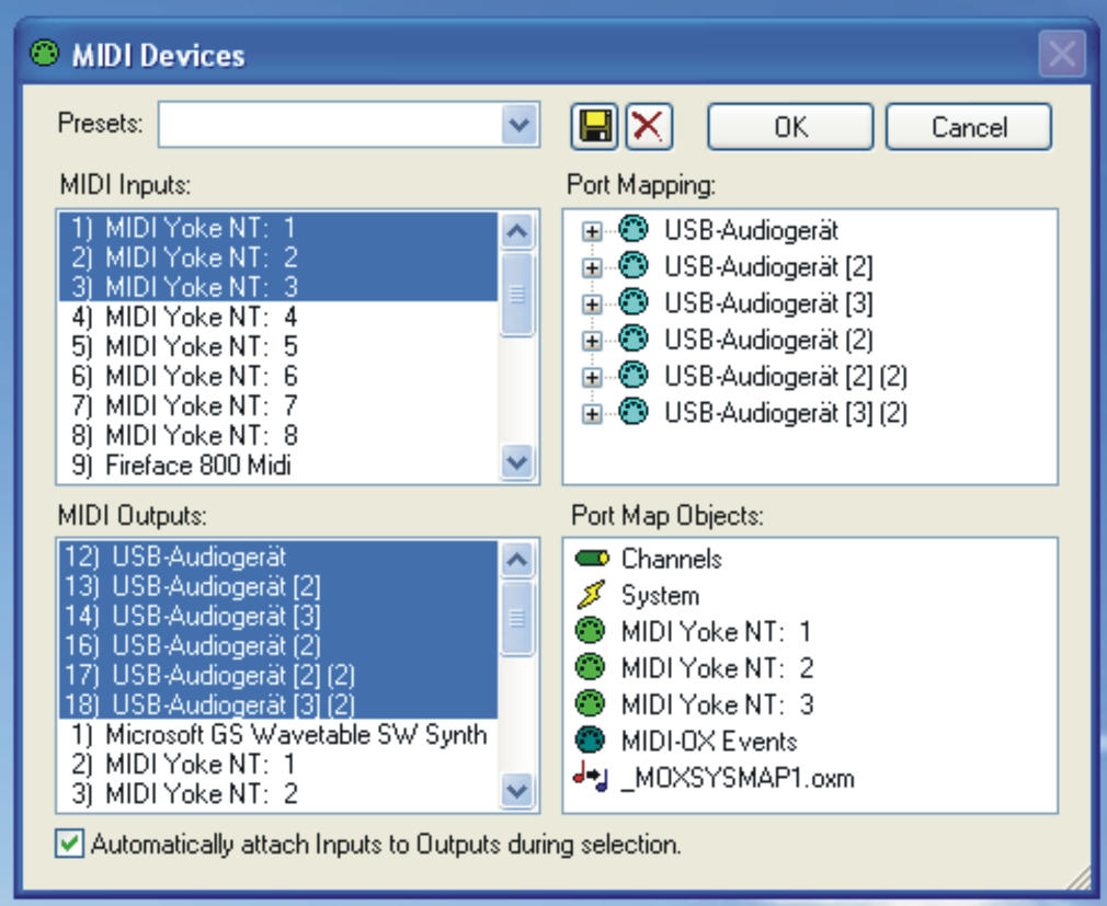
3. Start midi ox.
4. Load in the midi input directory midi yoke port1
,2 ,3
In the midi out
directory, the Us2400 ports 1,2,3 and the
3
ports from the core module.
5. In the
split window you can route now the midi yoke port
to the US2400 port and to the core module.
6. Switch off
the us2400.
7. Start the recording software again, don’t close midi ox.
8. Open a project.
9. Start the us2400.
10. Now it should work.
Be
sure that you don’t confuse the midi pots of us2400 and the midi
interface of the core modules
.
Under Nuendo the midi ports have often similar names. If you would use the midi in port of your midi
interface instead of the us2400,
Nuendo would crash complete.
Why do I have to
switch off US2400 when I start the recording software?
This is a
bug that I have not solved until now. It is because US2400 send
nuendo the
message to switch off the display function when you start nuendo or a project.So
if you start nuendo and the us2400 is switched on, you would see nothing on the
displays. But if you switch on US2400 after opening nuendo and the project,
us2400
has no possibility to
disable the displays. I`m working on a bug fix!
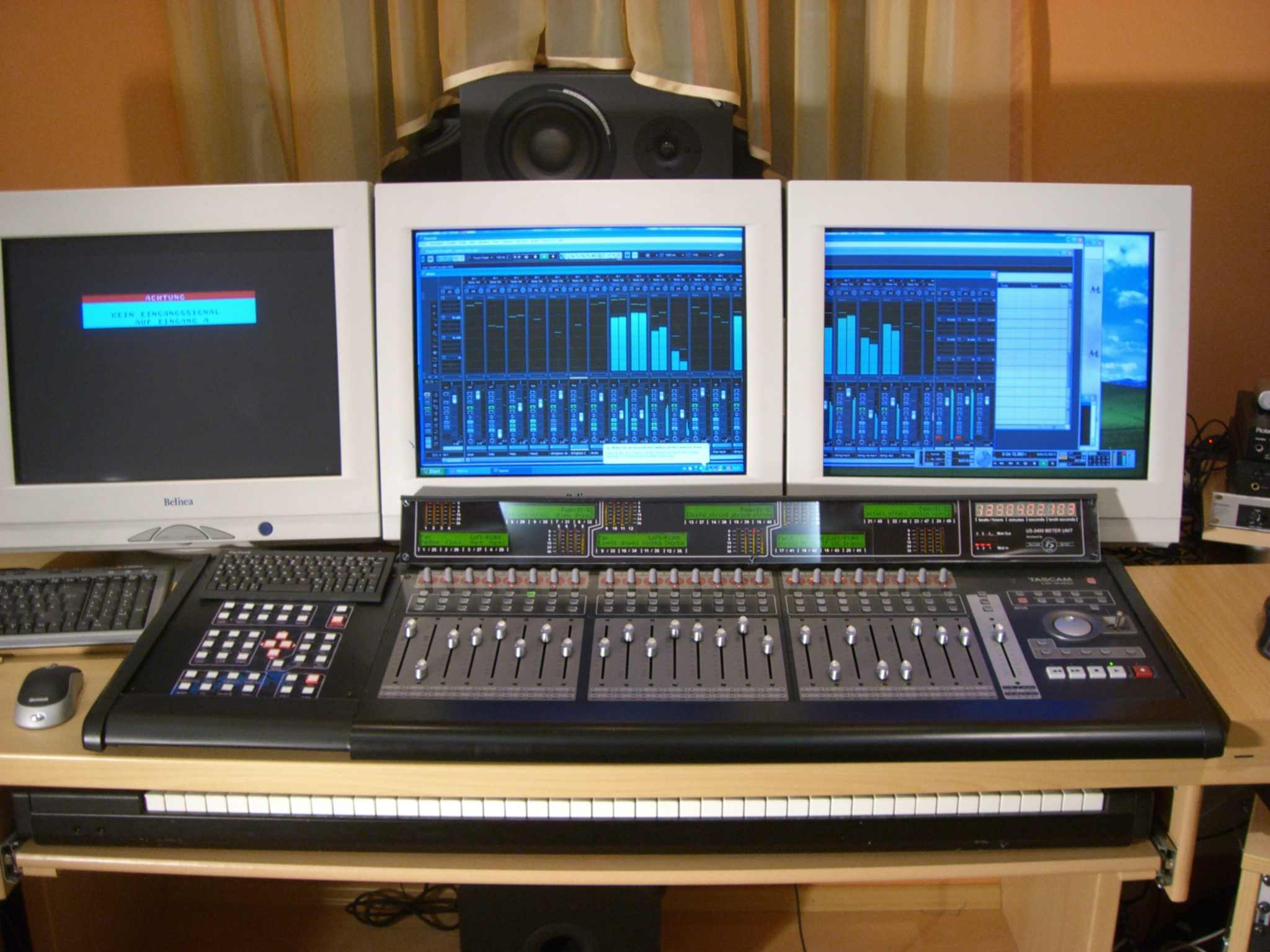
How to build the Case,
In the
following pictures
you can see how I
did the placement for the displays and the metering.
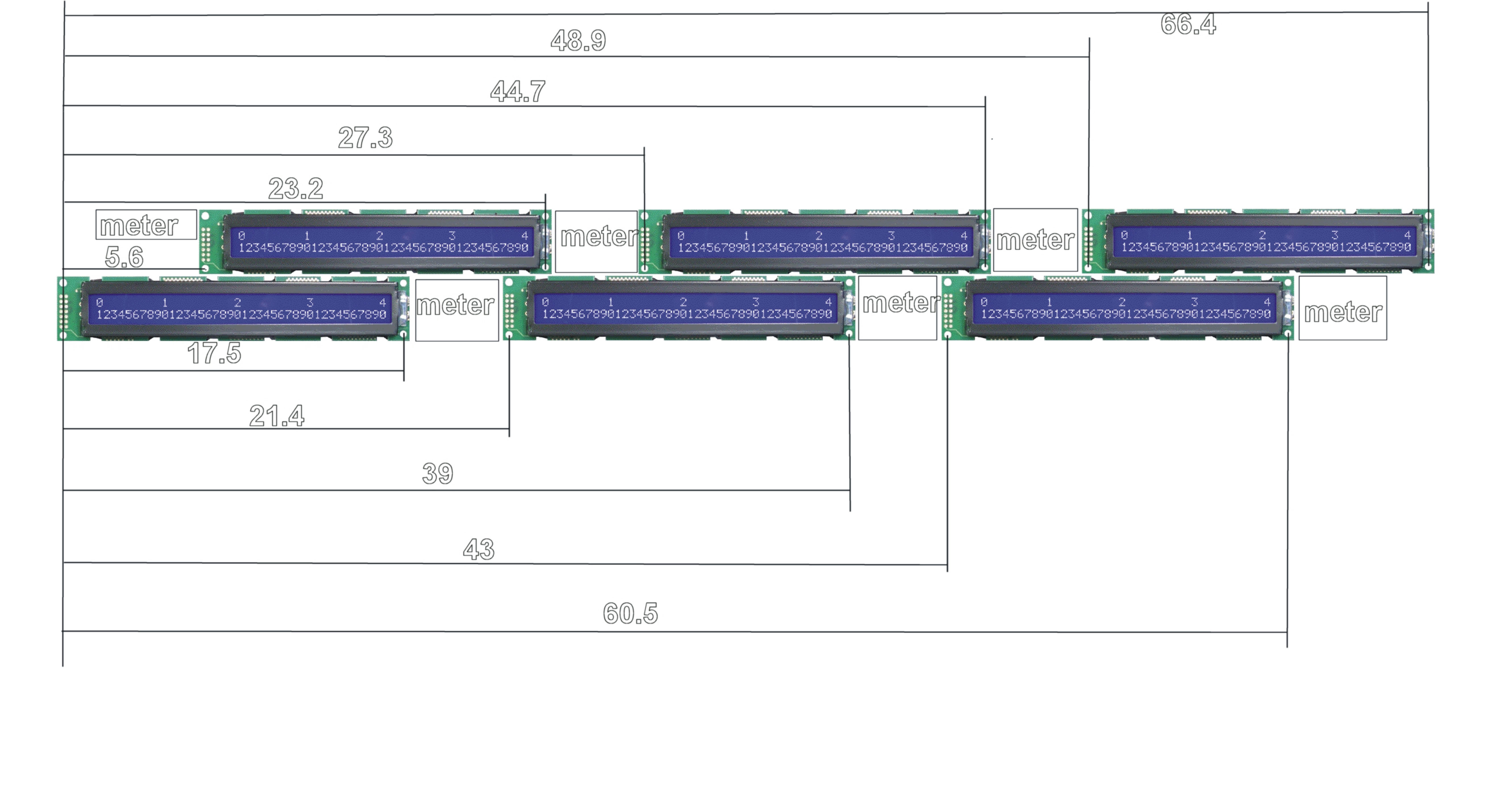
The metering is between the LCDs.
You can program the
position of each channel sign on the display if you edit the mackie emulation
software. So you are free to arrange the displays as you like. The reason why
used two 2x40 LCDs for 8 channels
and not one 2x55 LCD like the mackie control, is that the 2x55 LCDs are just
produced for the mackie control and there is no possibility to buy them.The Case
is made of steelplate, and on the front I used plexiglass. The graphic on the
front is printed out on paper and glued from the back side of the plexiglass.
The display section
is mounted with screws on the US2400.
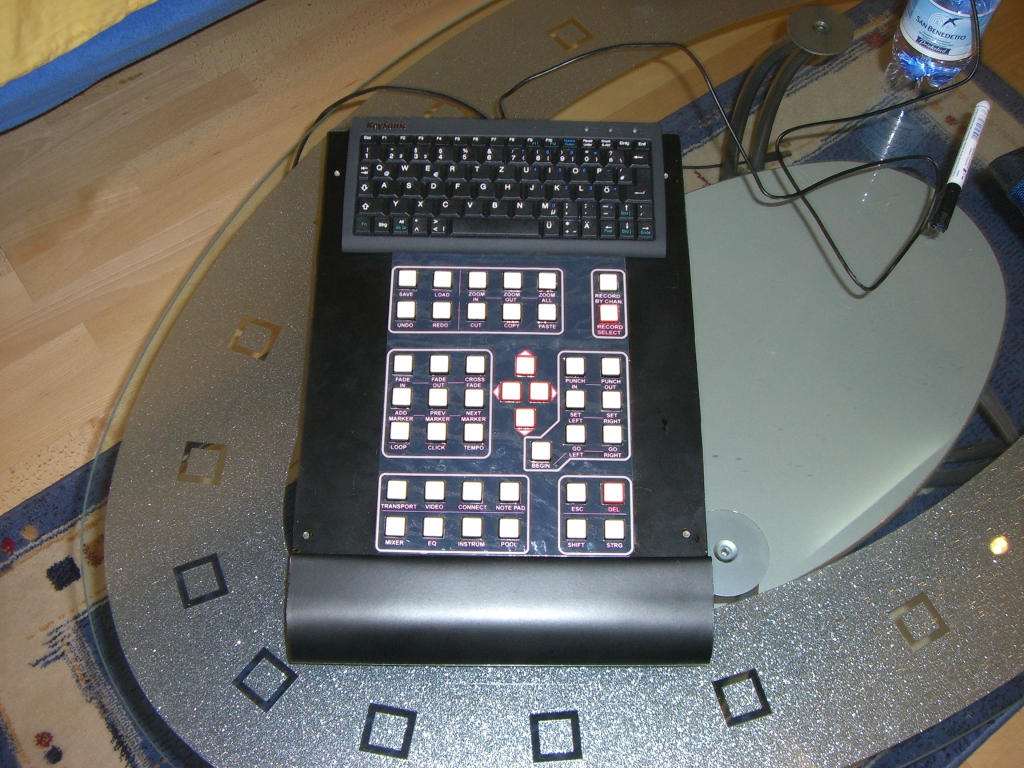
The short-key part of the mixer
For the short-key
part I have used an usb keyboard controller and instead of the
keyboard keys I have
built a board with switches and arranged it in a logical way
( this is a lot
better than the confusing steinberg keyboards). The case is also made
of steel plate and
it was built in the form of the mixer case. The graphic around the keys is a
laminated print out.
That’s it!
Good luck, and best regards,
Dietmar Spitzer
Great thanks, to all
the people of the MIDIBOX forum which made it possible that every one can build
his own daw-controller!
This people are doing a very good job and hopefully I could help with my
description for the US2400 controller too!
If you have any problems with your display unit contact the Midibox Forum, you can find a lot of trouble shooting descriptions there . http://www.midibox.org/forum/
If you have special
questions on US2400 and the display section you can contact me.
![]()
How to edit the mackie emulation
software.
Edit the position of
channel signs on the display:
In the lc_hlp.inc file you have to
edit the position value under the
Row Charcter LCD Position
Definitions
Switching the main
functions on or off ( metering, fader, knops, digits)
All this functions can be edit in
the main.asm file. There is a good description
for all functions in this file.
Visit also my recording studio homepage! www.tsrecords.at